


Correcting the off-axis wavefront aberration is potentially important for peripheral vision, for diagnostic imaging of the retina, and for influencing refractive development. A new technique called ocular wavefront tomography (OWT) was adapted to optimize the design of contact lenses to improve the eye's peripheral optical quality.
MethodsOWT is a technique for customizing a multi-surface model eye to mimic the off-axis wavefront aberrations for an individual eye. This technique was adapted for contact lens design by establishing clear design goals for the eye + contact lens system. To demonstrate the method we optimized the shape of an aspheric and bifocal contact lens to correct a wide angle model eye with −2D foveal myopia. Two strategies for correction reflected alternative design goals: 1) to fully correct central vision while also improving optical quality peripherally to enhance vision and retinal imaging, or 2) fully correct central vision while introducing a degree of peripheral myopia relative to central vision in order to slow myopia progression.
ResultsThe OWT technique successfully produced aspheric and bifocal contact lens designs over a wide field of view. In addition to correcting foveal vision, the optimized contact lens designs either 1) improved the retinal image quality across the visual field (< 45°) significantly to obtain a visual performance and retinal imaging benefit or 2) produced the desired level of myopia in the peripheral field to obtain a refractive development benefit.
ConclusionThe OWT technique is a validated tool to optimize contact lens design over a wide field.
la corrección de la deformación del frente de onda con desplazamiento de eje es potencialmente importante para la visión periférica, imágenes diagnósticas de la retina y repercutir en la progresión de errores refractivos. Se adaptó una nueva técnica denominada tomografía ocular por frente de onda (OWT, en inglés) para optimizar el diseño de lentes de contacto que mejoren la calidad óptica periférica del ojo.
MétodosLa OWT es una técnica que permite crear un modelo multisuperficial del ojo que imita las deformaciones de frente de onda con desplazamiento de eje para un ojo individual. Esta técnica se adaptó para diseñar lentes de contacto mediante el establecimiento de metas de diseño claras para el ojo + sistema de lente de contacto. Para demostrar el método, optimizamos la forma de una lente de contacto asférica y bifocal para corregir un modelo de ojo de ángulo amplio con miopía foveal de 2D. Dos estrategias de corrección reflejaron metas de diseño alternativas: 1) corregir plenamente la visión central mientras se mejoraba la calidad óptica periférica a fin de mejorar la imagen en retina y la visión, ó 2) corregir totalmente la visión central mientras se introduce un grado de miopía periférica respecto a la visión central para enlentecer la progresión de la miopía.
Resultadosla técnica de OWT produjo con éxito diseños de lentes de contacto asféricas y bifocales sobre un campo de visión amplio. Además de corregir la visión foveal, los diseños de lentes de contacto optimizadas 1) mejoraron la calidad de la imagen retiniana a través del campo visual (< 45°) de forma significativa y se obtuvieron beneficios en rendimiento visual y en la imagen retiniana, o 2) produjeron un grado deseado de miopía en el campo periférico que repercutía de forma beneficiosa en la progresión de errores refractivos.
ConclusionesLa técnica de OWT es una herramienta validada para optimizar el diseño de lentes de contacto en un campo de visión amplio.
Peripheral vision plays an important role in daily visual tasks such as driving1,2 and locomotion.3 Although visual acuity for reading letters and other spatial resolution tasks declines rapidly in the peripheral field, visual acuity for detecting spatial patterns and objects declines only slightly in the periphery.4–6 Consequently, peripheral detection acuity is nearly as sensitive as foveal resolution acuity to optical blur.7 Overcoming optical limitations of the natural eye across the entire visual field with advanced designs of contact lenses should therefore provide a significant visual benefit.
Recently clinical interest in peripheral vision has increased dramatically because of the possibility that peripheral optical aberrations (especially defocus and astigmatism) might be important for emmetropization and myopia development. Animal studies have demonstrated that eye growth due to experimental defocus or blurring by a diffuser is controlled by local retinal mechanisms.8,9 Likewise, animals that consistently experience near objects in their inferior field and distant object in their superior field tend to have longer axial length for the superior retina than for the inferior retina.10 The explanation of these results suggested by Wallman & Winawer9 is that myopic eyes are relatively hyperopic in the peripheral field compared to the central field because the eye is elongated along the optical axis. The homeostatic signals from the central retina that direct the eye to elongate less would be countered by signals from the peripheral retina that direct the eye to elongate more. Because the total number of neurons from the peripheral retina is large compared to central retina, the peripheral signal for elongation will dominate the emmetropization process and lead to myopia progression. Smith et al11–13 tested these ideas experimentally in primates and concluded that the peripheral retina can contribute to emmetropizing responses and to ametropias produced by an abnormal visual experience.
In spite of the importance of peripheral vision, the emphasis in contact lens optical design has centered on correcting foveal vision.14–16 Yet contact lenses are also capable of manipulating image quality in the periphery.17 In a theoretical study, Atchison fit a −4D myopic model eye with a spherical contact lens and an aspheric contact lens (conic constant −0.25). He found that the spherical contact lens introduced a relative myopic shift in the periphery but the aspheric contact lens eliminated such a myopia shift. That result demonstrated that contact lenses have the potential either to improve image quality in the peripheral retina or to introduce myopic refraction pattern in the periphery which may in turn slow the rate of myopia progression.18 However, little is known about how to design contact lenses for a wide field of view in order to realize these potential benefits. Similarly, the design of spectacle lenses to correct refractive error over the entire visual field has not yet been achieved although Smith and colleagues19 successfully optimized an ophthalmic lens to correct one meridian of a wide-angle schematic-eye.20
Classic optical design of contact lenses largely involves selecting surface shape so that the aberrations associated with foveal vision are minimized.14,15 Designing contact lenses to improve peripheral vision is more complicated because multiple objectives are possible. For example, apart from correcting central vision, the designs could either 1) improve peripheral retinal image quality significantly to obtain a visual performance and/or retinal imaging benefit or 2) produce a desired level of peripheral myopia to obtain a refractive development benefit. In this report we show how these two design goals can be achieved using a new technique called ocular wavefront tomography (OWT).21 The OWT technique was developed to create optical models of the eye that mimic the off-axis wavefront aberrations measured in individual eyes. Given such a model, the same technique can then be used to optimize the design of a contact lens (or other ophthalmic treatments such as spectacles, intraocular lenses, corneal inlays, etc.) for use in conjunction with the eye to achieve the desired optical behavior of the eye + lens system across the visual field.
The content of the paper is as follows. The Methods section describes how to adapt the OWT technique for contact lens design. The Results section illustrates the method by designing two types of contact lenses, one for each of the two goals listed above (optimizing peripheral image quality, or deliberately introducing field curvature for myopia control). The Discussion section briefly discusses the tradeoff between central and peripheral corrections, the formulation of design goals, and the modeling of human eyes across a wide field of view.
MethodsSummary of ocular wavefront tomographyOcular wavefront tomography (OWT) is a computational process for customizing a wide angle schematic eye to achieve the twin goals of anatomical accuracy and functional equivalence.21 Anatomical accuracy is achieved by constraining the parameters of the model to lie within acceptable limits. Functional equivalence is achieved by adjusting the model's parameters until the wavefront aberration function of the model along the foveal line-of-sight, and along multiple peripheral lines-of-sight, match the aberrations measured in an individual eye or some representative eye. The OWT procedure consists of four steps. Step 1 configures a generic model eye as an initial template that serves as a starting point for the optimization process. This initial model should include all of the anatomical features deemed important. Depending on the intended application, this template model eye might include a single refracting surface, or multiple surfaces, or a gradient index lens. Step 2 determines the wavefront aberrations of the eye along multiple lines-of-sight that adequately sample the range of visual field to be corrected. For example, a modified clinical Shack-Hartmann aberrometer22,23 or a scanning Shack-Hartmann Aberrometer24 could be used to obtain such aberration measurements in an individual eye. Alternatively, the eye might be characterized by aberrations of a typical eye across the visual field for a target population. Step 3 formulates a good measure of the dual customization goals (anatomical similarity and functional equivalence) in the form of a merit function (eqn. (1)) that quantifies the degree to which the current state of the model satisfies the design objective. The first part of the merit function represents the anatomical similarity between the customized model and the anatomical dimensions common to all eyes or, if available, the specific dimensions measured for an individual eye. The second part of the merit function measures the difference between the wavefront measurements of individual eyes along multiple lines-of-sight and the theoretical values obtained by ray tracing through the customized model. The relative weighting of these two parts, and of the various factors within each part, is flexible and application-dependent. 21 Step 4 formulates the tomography problem of adjusting the template model eye to become anatomically similar and functionally equivalent to the subject's eye into an optimization problem of finding a customized model eye that achieves a global minimum of the merit function. A variety of optimization techniques can be used for this purpose, including damped-least squares, simulated annealing, neural networks, case-based reasoning, and expert-system. These computational-intensive techniques solve the optimization problem iteratively.
Applying ocular wavefront tomography to the design of contact lenses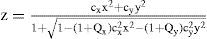
Given a wide-angle model of an eye, the OWT technique can be used to optimize the design of a contact lens used in conjunction with the eye. We do this by fixing the parameters of the eye model while optimizing the parameters of the contact lens to achieve the desired optical behavior of the eye + lens system across the visual field. Again the method involves four steps: the construction of a design template, the specification of design goals, the formulation of a merit function, and the optimization of the design. Steps 3 and 4 are the same as described above in section 2.1, but the first two steps require modification as described below.
To design a contact lens using OWT, the first step is to create a design template consisting of a generic contact lens in apposition to a fixed model eye. The parameters of this generic contact lens will be iteratively optimized while the fixed model eye remains unchanged as a master system in the template. The choice of model eye depends on the specific application. For example, to customize a contact lens for an individual eye, the eye model could be obtained from wavefront aberration measurements by the OWT technique, using the corneal topography data in the merit function to ensure accurate geometry of the corneal front surface. Alternatively to design a more generic contact lens for improving peripheral vision for a population of eyes, a statistical model of the eye based upon population data may be preferred. In the examples reported below, we used a published model eye20 to enable a comparison with known results from the literature.
The second step of OWT lens design is to specify the desired optical performances of the lens + eye system in central and peripheral visual fields. In this study, we developed two different design goals. Both goals aimed to optimize image quality (e.g. RMS of wavefront error) along the central line-of-sight, but they differed for the peripheral field. Test case 1 aimed to improve image quality in the periphery whereas case 2 aimed to manipulate the variation of peripheral refractive error across the visual field for the purpose of myopia control.
Design goals for wide field-of-view require defining the optical performance (e.g. wavefront error) along peripheral lines-of-sight, where oblique viewing of the iris causes the entrance pupil to appear elliptical. Several methods are available to define wavefront aberrations over elliptical pupils, which we compare and contrast elsewhere.25,26 Particularly for test case 2, in order to calculate the spherical refractive error along the oblique line-of-sight it was convenient to use the scaling method22,26 which stretches the elliptical pupil into a circle of constant diameter for all lines-of-sight. Zernike aberration coefficients obtained from the stretched wavefront map can be converted to spherical refractive error using the formula derived by Atchison et al (eqn. B24 in Atchison's paper27). By ignoring the higher order terms in the original equation, the formula becomes
where M is the means spherical refractive error in diopters, Cnm are the Zernike coefficients calculated from the scaling method, R is the radius of the circular entrance pupil, and φ is the angle between the peripheral and foveal lines-of-sight. Since the eye models in our examples have rotational symmetry, this eqn. (2) applies to any meridian. The desired variation of M with field angle φ specifies the design goal for peripheral refractive errors in test case 2.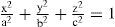
With the starting template set up in step 1 and rigorously formulated design goals in step 2, the merit function can be readily formatted in step 3. Similarly to the classic OWT approach, the first part of the merit function was formulated to measure the difference between the specified design goals and the ray tracing prediction of the design template (contact lens + model eye). The second part of merit function incorporates the mechanical constraints (e.g. edge thickness) of the contact lens from the fabrication or peripheral zone design. This merit function (Eq. (3)) is analogous to the merit function that measures the functional equivalence and anatomical similarity (Eq. (1)) of model eyes in section 2.1. The weighting inside and between each part of the merit function are flexible and can be iteratively adjusted during the design stage to achieve the balance of the design.28–30 After formulating the merit function, the optimization engine can be applied to find the optimal design that achieves the global minimum of the merit function in the final step.
Test cases
A rotationally symmetric, wide-angle model-eye20 was chosen as the fixed master system in the OWT design template. This widely cited model captures the main anatomical features of the human eye with minimum complexity. Besides a spherically curved retina, this model eye consists of four refractive surfaces: anterior & posterior cornea and anterior & posterior lens. The model exhibits realistic off-axis aberration performance at moderate field degrees (10°–45°).20,22 To simulate axial myopia (−2D, 550 μm), the length of the schematic eye was increased appropriately (posterior chamber length = 17.1005 mm). Entrance pupil diameter was set at 5 mm, which is large enough to include significant amounts of higher-order aberrations.
Test case 1 was a monofocal aspheric lens optimized to improve peripheral optical quality (RMS of wavefront error). The template contact lens used rigid material with a refractive index of 1.492. The back surface of the contact lens was spherical with the same radius of curvature as the anterior corneal surface. A thin tear film layer of refractive index 1.336 was placed between the anterior cornea and the posterior surface of the contact lens. The front surface of the contact lens for test case 1 was aspheric with a surface sag z given in Eq. (4),
where r is the radius of curvature, × is the radial coordinate in lens units, k is the conic constant and h is the radius of the optical zone.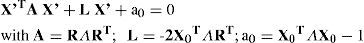
Test case 2 was a two-zone bifocal designed to correct the central vision and an outer annular zone designed to introduce relative myopic refraction pattern in the peripheral field. Its surface had sag profiles given in Eq. (5)
where rinner and router are the radii of curvature and kinner & kouter are the conic constants of the two optical zones respectively, × is the radial coordinate in lens units, h1 and h2 are the radii of the inner and outer optical zones. The constant C ensures the same sag value at the boundary between the inner zone and outer zones.ResultsTest case 1: Contact lens to improve the peripheral retinal image quality
The goal of test case 1 was to correct foveal wavefront aberrations while simultaneously improving peripheral image quality of the Navarro myopic eye (−2D) Since foveal vision correction is of high priority, 80 % of the weight was assigned to minimize the RMS of central wavefront. The remaining 20 % of the weight was equally assigned to reduce the RMS of the wavefronts along other oblique line-of-sight within 50 degree visual field. To prepare the starting design template, we fit the myopic model eye with an aspheric design (CV in table 1) that solely gives the diffraction-limited performance for the central vision. After OWT optimization, we found a design (PV in table 1) that corrects the central vision and meanwhile improves the peripheral image quality.
Summary of asphercial contact lens designs CV and PV. Parameters refer to equation (4)
| Design | r (mm) | k | h (mm) |
| CV | 8.0156 | −0.4223 | 4.97 |
| PV | 8.0536 | −0.1518 | 4.96 |
Figure 1 (a) shows the root-mean-square (RMS) off-axis wavefront error of lens + eye as a function of field angle of the myopic Navarro model eye. Design CV is a traditional design that only aims to correct refractive error in central vision (CV). This design provided diffraction-limited performance centrally and served as the starting template for optimization with OWT. Design CV also improved image quality in the near periphery (field angle < 30°) but image quality in the far periphery was actually worse with the lens than without for reasons described later. By comparison, the design PV gives priority to correcting foveal refractive error while simultaneously aiming to improve image quality for peripheral vision (PV). This design reduced RMS wavefront error along the foveal line-of-sight to 0.14 μm (1/4 wave) over a 5 mm pupil and improved peripheral image quality out to 45° visual field relative to the uncorrected eye. Design PV provided superior image quality compared to design CV for all peripheral field angles. The slight penalty for this improved performance in the periphery was a small residual wavefront aberration (1/4 wave RMS) along the central line-of-sight (compared to the design CV's diffraction limited central correction).
. (a) Root-mean-square (RMS) of wavefront errors (lower- and higher- order aberrations) as a function of field angle of peripheral lines-of-sight for Navarro myopic eye (empty triangle), the design CV (solid circle), and the design PV (solid diamond); (b) The spherical refractive errors along lines-of-sight for Navarro myopic eye (empty triangle), the design CV (solid circle), and the design PV (solid diamond).")
Performance of customized contact lens that improves the peripheral optical quality (5 mm on-axis entrance pupil, 550 nm). (a) Root-mean-square (RMS) of wavefront errors (lower- and higher- order aberrations) as a function of field angle of peripheral lines-of-sight for Navarro myopic eye (empty triangle), the design CV (solid circle), and the design PV (solid diamond); (b) The spherical refractive errors along lines-of-sight for Navarro myopic eye (empty triangle), the design CV (solid circle), and the design PV (solid diamond).
The primary effect of the contact lens is to change mean spherical refractive error M as computed by eqn. (2). As shown in Figure 1b, M is slightly larger for design CV than for design PV at the fovea, but M increases more rapidly with field angle for design CV than for design PV. The relatively small amount of refractive error in the periphery for design PV is the primary factor that accounts for the superior image quality of this design relative to the other two conditions shown in Figure 1a. Other factors (oblique astigmatism and higher-order aberrations) play a smaller, but significant, role also. Peripheral astigmatism becomes larger for design PV than design CV. The astigmatism of PV and CV at 50° field angle are 4.49 μm and 3.65 μm respectively. On the other hand, the coma term of design PV is about 25 % smaller than design CV. The net effect of these aberration change is superior peripheral optical quality for design PV compared to design CV as shown in Figure 1a.
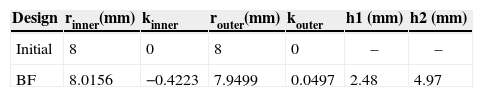
Test case 2: Contact lens to introduce myopic refraction patternThe goal of test case 2 was to correct foveal wavefront error while simultaneously changing relative peripheral refractive errors from hyperopic (in the Navarro model) to myopic (in the corrected eye). This optimized design (Design BF) is a concentric, two-zone bifocal design (Eq. 5) based upon the 5 mm on-axis entrance pupil of myopic model eye. Similar to test case 1, a merit function was set up with 60 % of the weight assigned to minimize the RMS of central wavefront error and the remaining 40 % of the weight was equally distributed over the peripheral lines of sight to manipulate the peripheral refractive pattern. The starting design template for this test case is summarized in the first row of Table 2. After OWT optimization, the bifocal (BF) design in Table 2 achieves the dual goals of correcting the central refractive error and changing the peripheral refractive pattern from relative hyperopia to relative myopia.
Summary of bifocal contact lens designs (BF). Parameters refer to equation (5)
| Design | rinner(mm) | kinner | router(mm) | kouter | h1 (mm) | h2 (mm) |
| Initial | 8 | 0 | 8 | 0 | – | – |
| BF | 8.0156 | −0.4223 | 7.9499 | 0.0497 | 2.48 | 4.97 |
The BF design achieved diffraction-limited performance (5 mm on-axis entrance pupil) along the foveal line-of-sight by using the inner zone to correct the myopic eye's on-axis wavefront error with an asphericity that produces negative spherical aberration to compensate for the eye's positive spherical aberration. The sign of peripheral refractive error of design BF remains hyperopic in the near-peripheral visual field (< 35°), but beyond 35 degree visual field, the sign changes to myopic. This pattern of peripheral refractive errors is markedly different from the CV design, for which peripheral refractive errors are always hyperopic. This result reveals the design flexibility provided by bifocal lenses for manipulating peripheral refractive errors.
One disadvantage of the bifocal design is that the slope of the surface is discontinuous at the boundary between inner and outer zones. This discontinuity is a disadvantage for fabrication of the lens and for achieving robust optical performance across different pupil sizes and different field angles. To avoid these problems, a transition zone is usually incorporated between the inner zone and outer zone for this purpose. We implemented a smooth transition zone by least-square fitting of the lens surface with a set of polynomials up to the 30th order. The RMS of the residual fitting error was 0.08 μm, which is negligible compared to typical fabrication tolerances. Residual refractive errors for this smoothed design (BF Smooth) were indistinguishable from the original bifocal design (BF). Smoothing increased RMS wavefront error slightly along the foveal line-of-sight from 0 (design BF) to 0.07 μm (0.13 wave, design BF smooth) over a 5 mm entrance pupil. Nevertheless, the peripheral optical quality of this design is better than the classic design CV within 45 degree field of view (Figure 2b).

Performance of customized contact lens that introduces a relative myopic pattern onto myopic eye's peripheral visual field. (a) Spherical refraction pattern of the Navarro myopic eye (solid square), design CV (solid circle), design BF (empty upper-triangle), and design BF Smooth (empty lower-triangle). (b) Root-mean-square (RMS) of wavefront errors (lower- and higher order aberrations) of the Navarro myopic eye (solid square), design CV (solid circle), and design BF Smooth (empty lower-triangle).
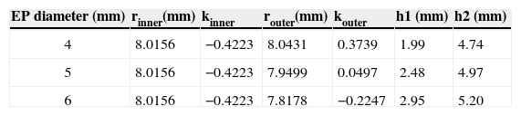
For bifocal lenses, the assumed size of the entrance pupil (EP) along the foveal line-of-sight is an important design parameter for determining the relative sizes of inner and outer zones of the lens. Moreover, the relative dimensions of the two zones affect the balance achieved between the central vision and peripheral vision corrections. The bifocal design BF reported in Table 2 was designed for the 5 mm EP of the myopic model eye. Applying the same OWT procedure to other pupil sizes, the bifocal lens optimized for a 4 mm EP or a 6 mm EP differ significantly from the 5 mm design as reported in Table 3. After smoothing these bifocal designs by polynomial fitting, we calculated their peripheral refractive errors. In each design, the peripheral refractive error varies only slightly with pupil size. Therefore the peripheral refractive error of each design reported in Figure 3a, which was computed at the design pupil size, is representative of all pupil sizes. Figure 3a reveals that the peripheral refractive error patterns of the “4 mm design” is more effective than the “5 mm design” or the “6 mm design” at introducing peripheral relative myopia. This is because the ‘4 mm design’ has a larger outer zone, which manipulates peripheral refractive error more effectively. The penalty of a small inner zone is reduced retinal image quality along the foveal line-of-sight when the actual EP becomes larger than the design size. This penalty is quantified by the modulation transfer functions (MTF) in Figure 3b. The MTF for the 4 mm design is significantly depressed for a 5 mm EP and even more depressed for a 6 mm EP. By comparison, the MTF provided by the 5 mm design is superior when the EP is 5 mm but once again becomes depressed if the EP exceeds the design size (e.g. 6 mm EP, 5 mm design pupil). Therefore, in practice, the relative dimensions of inner and outer zones of the bifocal should be selected carefully to achieve the desired balance between foveal image quality and peripheral refractive errors for habitual pupil sizes.
Summary of bifocal contact lens designs based on different entrance pupil sizes (4 mm, 5 mm, 6 mm). Parameters refer to equation (5)
| EP diameter (mm) | rinner(mm) | kinner | router(mm) | kouter | h1 (mm) | h2 (mm) |
| 4 | 8.0156 | −0.4223 | 8.0431 | 0.3739 | 1.99 | 4.74 |
| 5 | 8.0156 | −0.4223 | 7.9499 | 0.0497 | 2.48 | 4.97 |
| 6 | 8.0156 | −0.4223 | 7.8178 | −0.2247 | 2.95 | 5.20 |
 Relative peripheral refractive error of the 4 mm, 5 mm, and 6 mm designs when the entrance pupil size matches the design pupil size. (b) Modulation transfer functions (MTF) of foveal corrections for different combinations of entrance pupil sizes and design pupil sizes.")
Performance of customized bifocal contact lenses designed to introduce relative myopic pattern onto the peripheral visual field (a) Relative peripheral refractive error of the 4 mm, 5 mm, and 6 mm designs when the entrance pupil size matches the design pupil size. (b) Modulation transfer functions (MTF) of foveal corrections for different combinations of entrance pupil sizes and design pupil sizes.
In this study, we successfully applied the OWT technique to design contact lenses to correct a 4-surface schematic eye with axial myopia over a wide field of view. Besides correcting central vision, the two designs (PV and BF) reduce the myopic model eye's peripheral refractive errors reasonably well from different perspectives. The design PV improves the peripheral image quality over a ±45 degree visual field (Figure 1a) whereas the design BF effectively introduces a myopic pattern of refractive error in the model eye's far periphery (> 35°, Figure 2a). Through these two examples, we have demonstrated the effectiveness of optimize contact lens design via OWT.
One important aspect of applying OWT to design contact lenses is to achieve a balance among various design goals, especially between the goals related to central and peripheral vision. Since these dual design goals are competitive, achieving balance between them requires adjusting the weighting of the corresponding operands in the merit function. For example in test case 1, if the operands related to central vision are weighted 100 %, the OWT optimized design will be the classic aspheric design CV (Figure 1 in section 3.1) that achieves diffraction-limited correction centrally but only improves peripheral image quality to a limited extent. If 80 % of the weight is assigned to the operands for central vision and 20 % of the weight is assigned to the operands for peripheral vision, then OWT achieved a balanced design PV, which has slightly worse foveal correction (1/4 wave RMS) but effectively improves peripheral image quality up to 45 degrees. Usually this weighting adjustment procedure is iterative, the essence of which is similar to lens design.28,30
Another important aspect of applying OWT to design contact lenses is the generality of specifying design goals. Although the on-axis and off-axis wavefront aberrations in object space were adopted to formulate the merit function in this paper, other indicators of image quality can also be adopted. For example, the MTF can be used to represent the correction along the foveal lines-of-sight. The peripheral spherical correction in image space25,31,32 or peripheral through-focus33 can be used to indicate peripheral optical quality too.
We demonstrated efficacy of the OWT method by designing contact lenses to correct a schematic eye that is representative of typical human eyes. Although the emmetropic version of the Navarro wide-angle model-eye overestimates the on-axis spherical aberration and achieves little agreement at small angles, it nevertheless agrees with the experimental data reasonably well at moderate field angles (10–40 degrees).20 The myopic version of this model also predicts the relatively hyperopic shift in the periphery (Figure 2). Therefore it is a reasonable model to be used as a master system in the design template to demonstrate contact lens design for wide field of view. More sophisticated model eyes (e.g. myopic model eyes17) could also be used. However individual variability in wavefront aberrations across the visual field may require the use of customized wide angle model eyes21 as the master system. These customized model eyes in general are rotationally asymmetric, which suggests that optimization based on multiple semi-meridians is required. Nevertheless since the OWT procedure is a general framework21, it is relatively straightforward to generalize the application of OWT to design contact lens based on one or more semi-meridians.
Besides applying OWT to optimize the design of contact lens to achieve desired optical performance, it is also important to budget appropriate tolerance for how the lens interacts with the eye. In general, the misalignment of a contact lens on the eye affects both central and peripheral corrections. The sensitivity of the peripheral corrections to the misalignment is comparable to that of central correction. Furthermore, due to the high priority assigned to correcting central vision, the primary goal of tolerance analysis for wide angle designs should also aim to ensure good optical correction along the central LoS. From this perspective, the tolerance analysis for wide angle designs is similar to the analysis for the classic contact lens designs that focus solely on central vision correction. However, since the wide angle designs usually realize their benefit for peripheral vision by compromising slightly in correcting central vision, they usually have tighter tolerance than the classic designs. For example, the smoothed bifocal design (‘BF Smooth’) reduced the RMS wavefront error to 0.07 μm (0.13 wave) over 5 mm entrance pupil, which is worse than diffraction-limited correction of classic CV design. To ensure RMS wavefront error within 0.13 μm (1/4 wave), the classic design CV tolerates the decentration of up to 0.4 mm, while the smoothed bifocal design tolerates much less decentration (0.14 mm).
In this study, we introduced the OWT technique for designing contact lens and demonstrated its effectiveness through the two examples in the result section. Yet a successful contact lens design needs to achieve optimal performances among multiple design goals. Some of these goals may include the optical performances of the corrected eye for polychromatic light, various pupil sizes, through-focus performance, and mechanical stabilization on the cornea. Modern contact lens design is a framework for finding practical and balanced solutions to this multi-dimensional problem. We regard the OWT technique as a subset of this larger framework that stresses realizing the benefit of correcting peripheral vision of human eyes.
Conflict of interestThe authors have no proprietary, financial or commercial interest in any material or method mentioned in this study.
Funded in part by NIH grant NEI R01 EY 05109 awarded to Larry Thibos.


